Endless Improvements

العربية

Friction and Wear of Engine Parts
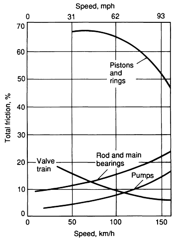
At a typical engine speed, the major engine friction components in order of importance are:
Piston ring assembly.
Valve train.
Crankshaft (bearings)·
Oil pump
The percentage of friction increases with increasing speed for the crankshaft bearings, connecting rod bearings, and pumps; the friction percentage decreases for the piston and ring assembly and the valve train assembly.
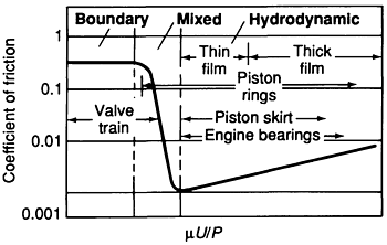
A difficult problem in understanding engine friction is the wide variation in the magnitude of the friction forces observed. The coefficient of friction ranges from 0.2 for boundary lubricated engine components to 0.001 for hydrodynamically lubricated engine components.
The critical elements in the valve train, including the cam-lifter interface and rocker-arm pivots, operate in the boundary to mixed regime, because high loads are encountered at low sliding speeds.
Piston rings operate over the range of thick-film hydrodynamic to mixed lubrication, because the gas load and velocity of the piston ring vary extensively over one engine cycle. At top dead center of the piston stroke when the gas forces are maximum, the velocity of the piston ring is zero and contact occurs between the piston ring and the cylinder wall.
The piston skirt, because of its large contact area and low loading, is primarily a thin film hydrodynamic contact.
Engine bearings operate in the hydrodynamic mode, except for brief periods during starting and stopping.
All reciprocating engines operate with lubrication. Oil of the wrong viscosity or oil that deteriorates in service can have a decided influence on wear of cylinders, cylinder liners, rings, camshafts, and valve trains. The mechanisms associated with engine wear included:
Corrosive wear: Due to the products of combustion of fuels.
Abrasive wear: Cams, rocker arms, and tappets.
Adhesive wear: Cylinder liners and piston rings.
Pitting caused by fatigue wear: Cams and tappets.
Scuffing: cylinder liners and piston rings.
Pistons and Piston Ring Assembly:
Among the many moving parts in an internal combustion engine, the piston and piston ring assembly are considered to be the components that contribute most to total engine friction and wear (about 25% to as much as 75%). It is estimated that piston ring friction amounts to approximately 50 to 70% of the friction loss of the piston assembly.
Pistons
Most pistons for automotive applications are made from aluminum alloys. The universal acceptance of aluminum alloy pistons by gasoline engine manufacturers can be attributed to their light weight and high thermal conductivity. Aluminum automotive pistons generally are permanent mold castings.
Passenger car engines pistons included: an aluminum-silicon alloy that has a good combination of foundry, mechanical, and physical characteristics, including low thermal expansion.
Heavy-duty engines pistons included: 336.0-T551, a low-expansion alloy, and 242-T571 because of its higher thermal conductivity and superior properties at elevated temperatures.
| Alloy | Unit | Si | Fe | Cu | Mn | Mg | Cr | Ni | Zn | Ti | Al |
| 336.0 | wt. % | 11-13 | 1.2 | 0.5-1.5 | 0.35 | 0.7-1.3 | – | 2-3 | 0.35 | 0.25 | Bal. |
| 242.0 | wt. % | 0.7 | 1 | 3.5-4.5 | 0.35 | 1.2-1.8 | 0.25 | 1.7-2.3 | 0.35 | 0.25 | Bal. |
Chemical compositions of cast aluminum piston alloys
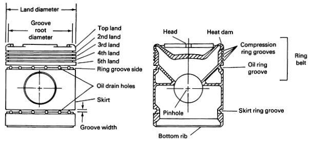
Cross section of a piston
Pistons Ring
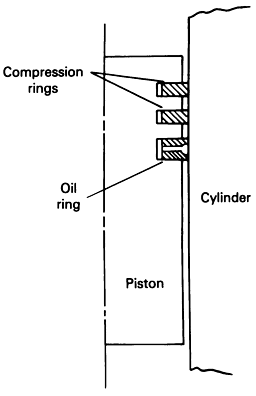
Piston rings are mechanical devices used for sealing pistons, piston plungers, reciprocating rods, and so forth. In gasoline and diesel engines, they are generally split-type, self-expanding metal rings. When they are placed in the grooves of the piston and provided with a lubricant, a moving seal is formed between the piston and the cylinder bore (liner).
Piston rings are divided into two categories: compression rings and oil-control rings.
Compression rings have to perform two basic functions gas sealing and oil control under the most hostile conditions, being exposed to high temperatures, high gas pressures, extreme stresses, impact, corrosion, and abrasion. They must be able to operate with a minimum of lubrication and still provide service at low wear conditions. Therefore, the basic design considerations are efficient sealing, light weight, and good material strength and minimum wear under elevated-temperature conditions.
Oil rings, generally one or more, are placed below the compression rings to prevent the passage of excessive lubricating oil into the combustion chamber, yet provide adequate lubrication for the compression rings. Major factors affecting this basic function are ring-bore contact pressure, ring-bore conformability, sliding surface characteristics, and drainage for the surplus oil. Other factors that influence oil ring design include amount of oil transported, oil viscosity, and engine operating and temperature conditions.
An ideal piston ring, material must meet the following requirements: low friction and wear losses, superior scuffing resistance, tolerances for marginal lubrication and rapidly varying environments, good running-in wear behavior, long-term reliability and consistency of performance, long maintenance free life, and low production costs. Although no single material can meet all of these requirements, base materials exhibiting good strength, fatigue, impact, and wear properties can be coated with materials that have excellent wear, friction, and scuff-resistance characteristics.
Gray cast iron, with a hardness ranging from 200 to 400 HB, is the most commonly used material for compression and oil rings. In heavy-duty engine applications, alloy cast iron, ductile iron, and malleable iron are used. Harder materials, such as carbon steel or even bearing steels, may also be used.
Relatively thick coatings (up to 0.2 mm) of plated chromium on the ring periphery provide the best compromise between scuffing, wear, and corrosion resistance and low friction and oxidation resistance at high temperatures. Generally, the use of chromium-plated top rings (with a hardness of 700 to 900 HV) run against cast iron cylinder liners can reduce the ring and liner wear by a factor of 2 to 3. Rings coated with flame- or plasma-sprayed coatings of molybdenum (in thicknesses up to 0.25 mm, or 0.01 in.) with a hardness of greater than 1000 HV are believed to have higher scuffing resistance than chromium-plated rings. The major limitation of molybdenum ring coatings is that they are subject to oxidation at 500 °C, and at 730 °C the oxide volatilizes.
Ceramic (Cr2O3), cermet (WC-Co, Cr3C2-Ni, and Cr3C2-Mo), and alloy (Mo-Cr-Ni) plasma-sprayed coatings have also been developed for achieving improved wear and scuffing resistance under conditions of marginal lubrication.
Cylinder Liner
The cylinder walls are stressed mechanically by the high gas pressure and the side thrust of the piston, as well as thermally by the high gas temperature. Because all these stress-induced factors are cyclic, the cylinder liner materials must have good mechanical and fatigue strengths; otherwise, cylinder bore distortion or early material fatigue failure may result. In addition, tribological properties such as wear and scuff resistance must be satisfactory, because metal-to-metal contacts between piston rings and the cylinder liner do occur.
Most cylinder liners are made of gray cast iron. To increase their mechanical strength, additions of nickel, chromium, copper, and molybdenum are required. The addition of at least 0.3 wt% Cr to improve wear resistance is fairly common and is considered to be particularly beneficial when combined with 0.65 wt% Mo.
Steel cylinder liners also have been used, offering the advantage of much thinner walls. They must be hardened to at least 400 HB, however, for satisfactory resistance to wear and scuffing, or else be chromium plated. It should be noted that chromium-plated liners should not be run against chromium-plated piston rings, but rather against plain cast iron rings or rings with other types of coatings.
Aluminum alloy A390.0 cylinder liners with high silicon content (~17% Si) have also been used. Some engine test results show that the liner wear of cylinders made from this material is lower than that of conventional cast iron liners
The surface finish of the cylinder bore is another key factor influencing oil consumption, scuff and wear resistance, and engine life. Generally a clean, burr-free, consistent surface finish is required. An average surface finish of 0.5 to 0.8 μm is recommended.
Piston Ring – Cylinder Liner Scuffing:
For piston rings and cylinder liners, scuffing is primarily the result of the breakdown of the lubricating oil film separating the sliding surfaces. This leads to metal-to-metal contact, causing local welding between the ring and the liner.
Piston ring scuffing is generally a running-in problem and is particularly likely to occur if full load and speed are applied too rapidly. It can also occur after longer running periods if the lubrication conditions deteriorate. The symptoms of scuffing in an engine are usually high oil consumption and blow-by, and sometimes a noticeable engine knocking noise. If scuffing is allowed to proceed, it may cause piston seizure or a major increase in piston clearance, resulting in a heavy knocking noise. However, in some cases the prime scuffed area does not spread, but heals itself, and the engine is still able to perform satisfactorily. Some of the methods used to reduce the incidence of scuffing include:
Fitting the piston rings with the running surface pre-shaped to a profile resembling that obtained after running-in so that less running-in wear is required.
Providing a surface finish on the cylinder liner that is coarse enough to increase the wear rate of the rings. If the rings are pre-shaped, however, the finish should be made finer than if they are flat.
Providing a surface finish on the cylinder liner that is coarse enough to increase the wear rate of the rings. If the rings are pre-shaped, however, the finish should be made finer than if they are flat.
Using a small amount of mildly abrasive material as a coating or filling on the liner or rings that will help to maintain an adequate initial wear rate.
Increasing the oil supply to the upper rings during running-in, which helps flush out wear debris and counteract any local deficiencies in the oil distribution.
The principal factors that influence wear of piston rings are speed, temperature, load, frequency of use, dirt, corrosion, surface finish, and quantity of lubricant.
Reducing Piston Ring Assembly Friction
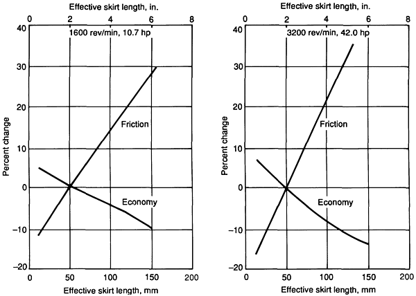
The light loads and large contact areas associated with the piston skirt promote a hydrodynamic contact. In order to reduce a hydrodynamic friction, skirt areas have been reduced in recent designs. Decreasing the effective skirt length from the original design length reduces friction and improves engine economy for both low-speed, low-load and high-speed, higher-load operation.
Substantial reductions in ring friction can be realized by reducing ring tensions and face widths.
Valve Train Assembly:
The valve train assembly includes such components as the camshaft, cams, tappets (hydraulic lifters), valves, valve seat rings, valve springs, and rocker arms.
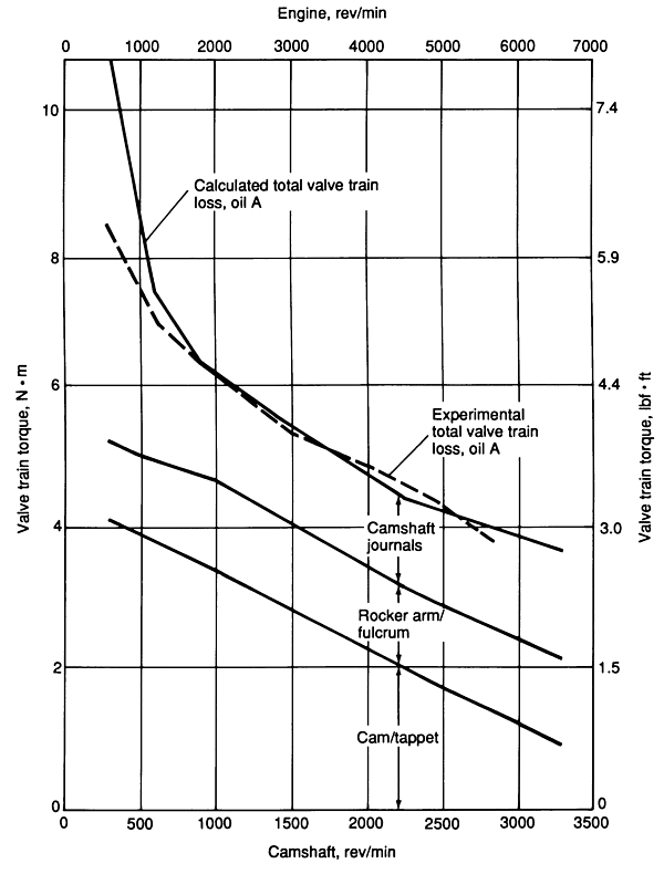
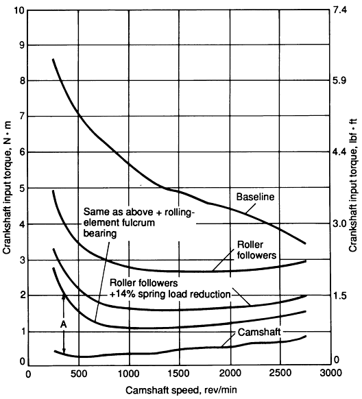
As the camshaft rotates, the cams use pushrods and rockers to operate the cylinder valves, which admit the fuel or expel the exhaust gases. In an overhead camshaft engine, the cams lie above the valves and move them directly. It is estimated that as much as 25% of total engine friction losses are attributable to the valve train assembly. Contributions of specific components to valve train friction torque loss are:
Valve Train Friction
Valve train design presents a challenge because high loads must be carried over the entire speed range of the engine. Loads acting on the valve train at low speeds are caused primarily by valve spring forces, while at higher speeds inertia forces generated by component mass dominate. There are several valve train as below:
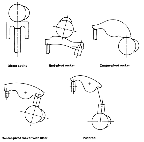
The torque required to drive the valve train is lowest for the direct-acting design. This is because there is only one sliding contact. The other design alternatives exhibit high friction because of the additional rocker-arm pivot loss.
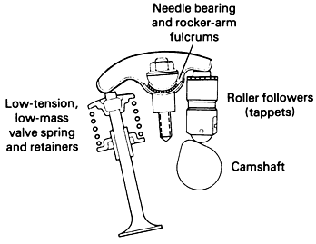
One effective method of reducing valve train friction is to use rolling-element bearings at critical locations. Such bearings are well suited to carry high loads at low speeds. Such designs have been used in racing engines. Rolling element bearings are included at the cam-lifter interface, the rocker-arm pivot, and the interface between the rocker nose and the valve stem.
Studies have shown that the valve train torque can be reduced by as much as 50% at 1500 rev/min using rolling-element bearings; the projected vehicle fuel improvement is 2.9%. Cam roller-followers of silicon nitride and partially stabilized zirconia are beginning to find application in diesel and automotive engines because they can replace a needle-bearing-type roller with a single, simpler rolling element, thereby reducing the weight of the engine. Disadvantages of the rolling-element bearing design include the susceptibility of the bearings to rolling-contact fatigue and increased complexity and cost.
An alternative to the rolling-element bearing approach is a reduction in valve spring load. The projected improvement in fuel economy is about 0.5%.
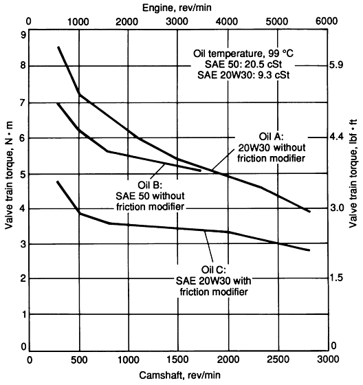
The oil viscosity has a relatively small effect on overall friction loss, but that a marked reduction in friction can be obtained with oils containing friction modifiers, or additives. Selection of the proper lubricant may reduce friction levels to those obtainable by component redesign.
| Oil | Viscosity, cSt | Elemental Composition, ppm | Friction Coefficient | |||||
| @ 40°C | @ 100°C | Zn | P | Mo | Mg | B | ||
| A | 76.3 | 9.2 | 1308 | 1185 | – | 1190 | 141 | 0.1 |
| B | 269.5 | 20.5 | 1767 | 1612 | – | 1496 | 169 | 0.1 |
| C | 77.6 | 9.3 | 1243 | 1099 | 1998 | 998 | 125 | 0.05 |
Valve Train Wear:
As with friction, the cam-tappet interface is also the most critical wear consideration. Under heavy duty, cams and tappets suffer from burnishing (due to adhesive/abrasive wear processes), scuffing (due to severe adhesive wear processes), and pitting (due to fatigue wear processes). The wear modes for cams and tappets are very similar to those for gears.
The wear of cams and tappets can be reduced considerably by selecting hard material combinations or by hardening the cam material by heat treatments, thermochemical treatments, or by applying coatings.
Harden-able gray iron camshafts (SAE Grade G4000d) are the most widely used; steels may be water-quenched carbon steels, oil-quenched alloy steels of 0.5 to 0.7% C, or a carburizing grade.
The most common tappet material for automotive applications is gray cast iron of composition similar to the following: 3.20% C, 2.25% Si, 0.80% Mn, 1.10% Cr, 0.60% Mo, 0.55% Ni, 0.20% max P, and 0.10% max S.
Ceramic materials such as silicon nitride are finding increased use as tappet shims and wear pads.
Silicon nitride valves, while currently expensive, have been used very successfully in high-performance racing engines. Their low mass and high stiffness allow them to be used at the high speeds (>10,000 rev/min) typical of such engines.
Crankshaft Bearings:
Large loads are carried by hydrodynamic journal bearings with low energy losses during the engine cycle because of the complete separation of the two rubbing surfaces by a fluid film. Loads on crankshaft journal bearings vary in magnitude and direction because they are composed of inertial loads caused by compression and expansion events. Bearing clearance and journal diameter are two important parameters that are controlled during the engine design process.
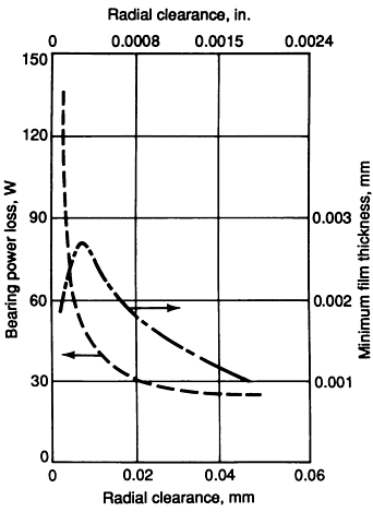
Bearings Clearance
As clearance increases, the bearing friction loss decreases, while the minimum film thickness exhibits a local maximum. Durability considerations suggest that to prevent bearing wear, maximum film thickness must be maintained. Thus, most journal bearings are designed to provide film thicknesses on the order of 2.0 μm. The friction power that could be saved by increasing journal bearing clearance beyond this maximum film thickness point is overshadowed by requirements for maintaining an adequate minimum oil film thickness.
Journal Bearings Diameter
Journal bearing diameters also significantly affect bearing power loss. The decreasing the rod journal diameter results in a 3 to 4% reduction in engine friction and a corresponding 1% improvement in fuel economy. It should be pointed out, however, that bearing diameter also controls the torsional strength of the crankshaft. Therefore, a design decision must be made between decreasing bearing diameters to reduce friction and the resulting loss in crankshaft strength.
Oil Pump:
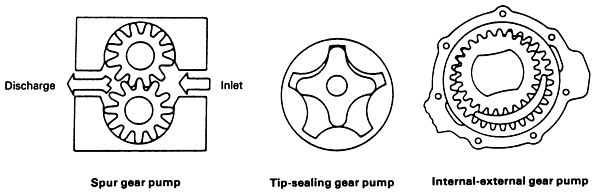
The types of oil pumps generally used in engines are the spur gear, internal-external gear, and tip-sealing gear.
These gears are typically driven at engine speed or half engine speed. Pump choice and drive ratio are usually dictated by available design space (especially length) and the selected drive mechanism. Once the location and drive are determined, noise, pressure fluctuations, cost, and efficiency trade-offs are considered.
Engines with the camshaft in the block typically have a common drive shared by the distributor and oil pump; spur gear of tip-sealing pumps are used in such applications. These pump designs have relatively small diameters, which minimize friction losses between the gear outer diameter and the housing.
Engines with overhead camshafts have no convenient half-speed oil-pump drive, especially if the distributor is driven from the camshaft. In this case, the designer must choose between providing an auxiliary shaft at extra cost or installing the pump on the crankshaft. The crankshaft option is usually selected for cost considerations, but the length of the pump is normally limited. This in turn forces selection of a thin pump (usually an external-internal gear type) with a large-diameter gear to provide the required displacement. The diameter of the outer gear is a function of the inner gear size required to go over the crankshaft. The large diameters of crankshaft-driven pumps result in higher losses because of the increased frictional torque.
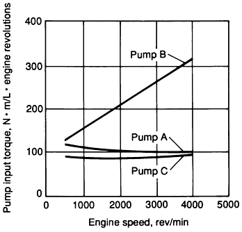
Comparing the input requirements measured for different pump designs:
Pump A: tip-sealing gear, half-speed drive, 67 mm diameter.
Pump B: internal-external gear, engine speed drive, 100 mm diameter.
Pump C: tip-sealing gear, half-speed drive, 41 mm diameter.

Facebook Comments